AVR's ATTiny Series are packaged in a space saving 8-pin case and can easily be programmed via their ISP interface.
Here are some programs to cover some small tasks , all built with AVR Studio 4.
Click the pictures to obtain the full scale view.
PLLControl (Assembler)
program the wireless block of an older home phone from Panasonic with an ATTiny 13. Channel switching through pushbutton.
This is the receiver code, as i planned using the RF blocks for a wireless bass guitar system. The transmitter is similar.
the project was never finished as a bluetooth connection is more desirable now.
Program more about the M54958 PLL chip
----------------------
RandomLights (Assembler)
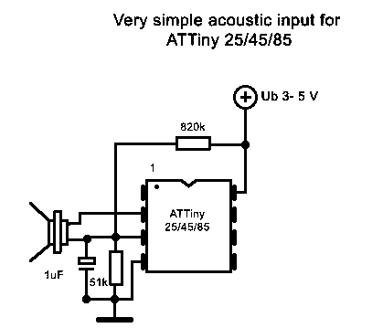
This project is now a lot more than only a random light generator. It uses the built in A/D converter of the ATTiny 25/45/85 to control 18 lights forming a circle.
Output clock and data lines are connected to a series of 3 CD4015 shift registers as LED output drivers.
Advance through the modes including power off/sleep with a single button. I used a notebook speaker mounted in the case which is sensitive enough to react on tapping the case. The input network pulls the internal opamp away from the ground rail.
Program
------------------------
SolderingStation (Assembler)
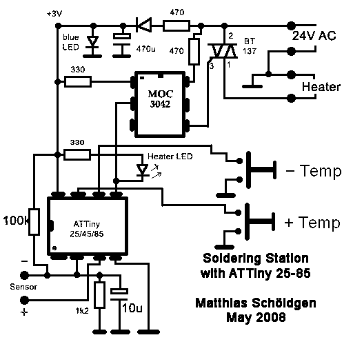
When the controller of my soldering iron broke i had to do something. As the ATTiny 25/45/85 contain an analogue amplifier and A/D converter capable of amplifying the weak signal from a thermocoupled element i decided to use it for controlling my iron. This project uses the A/D converter in 10-bit mode with differential input to regulate the iron to one of 5 preset temperatures.
User input is interupt driven with pushbuttons to increment or decrement through the settings. Feedback is done by flashing the heater LED.
A blue LED serves as power lamp and voltage stabilizer. Any 2.7 - 5 Volt zener would do here but i have masses of those LEDs . The input network is for pulling the internal opamp out of rail-to-rail operation which is doesn't do good. Automatic zerocross-switching the heater is accomplished by using a MOC3042 optocoupled triac in the AC circuit. Note that a MOC3043 will work here,too, as will a TL3043. Thanks to Kestutis for letting me know!
Program
----------------------
Replacing a HS1527 RemoteController with ATTiny25/45/85 (Assembler)
The HS1527 is a One-Time programmable remote transmitter chip where each chip carries a unique ID (address). But for my home i needed more than one handheld transmitter with the same coding. As the HS1527 comes in a 8-pin DIP case a ATTiny would fit into the housing of the transmitter. Pinning on the HS chip is strange, though, but with shifting the Tiny one pin up, cutting a few PCB traces and wiring the remaining pins with wire-wrap i was able to replace the chip and even mount a socket for the Tiny.
The timing was decoded and the program for the Tiny adjusted so that it resembles the original coding of the HS1527 closely.
One other problem was to solve: The HS1527 is powered by the 12 Volt lighter battery directly while the Tiny will not work with anything higher than 5 Volts. A 6.8 volts zenerdiode in series with the supply solved that. The program is straightforward. When the Tiny is powered up it scans the keys and by a lookup-table translates it into a valid transmission code.
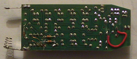
Pictures of the modified transmitter. I removed the oscillator resistor for the HS1527 to make place for the Tiny. Note how the MC is shifted one pin up to match most of the pins:
A look on the back side. The trace below the zener is cut. This transmitter powers the chip only when a button is pressed, so the program won't need sleep mode. I moved two pullup resistors from the top to the bottom to make place for the MC.
Program
----------------------
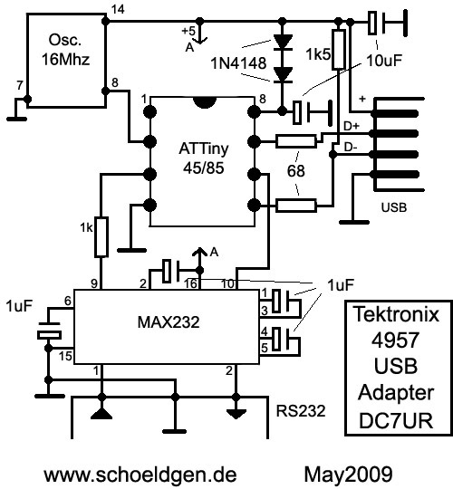
USB Interface for Tektronix 4957 tablet using V-USB ( C )
The availability of the V-USB library made it possible to create an USB adapter for connecting this old quality digitizer tablet to modern machines. The tablet is a huge device with high resolution and a 12" by 12" inch working area. The device appears as a HID-mouse device with absolute coordinates. The software mostly consist of the V-USB routines and an interrupt-driven serial receiver. The ATTiny acts as a code converter and also initializes the tablet. Source code is well commented. The ATTiny is operated from an external 16 Mhz oscillator and should be fused to no CLKDIV, ExtClk (on PB3). No drivers required. Built with AVRStudio 4 and WinAVR (gcc).
Project ZIP
----------------------
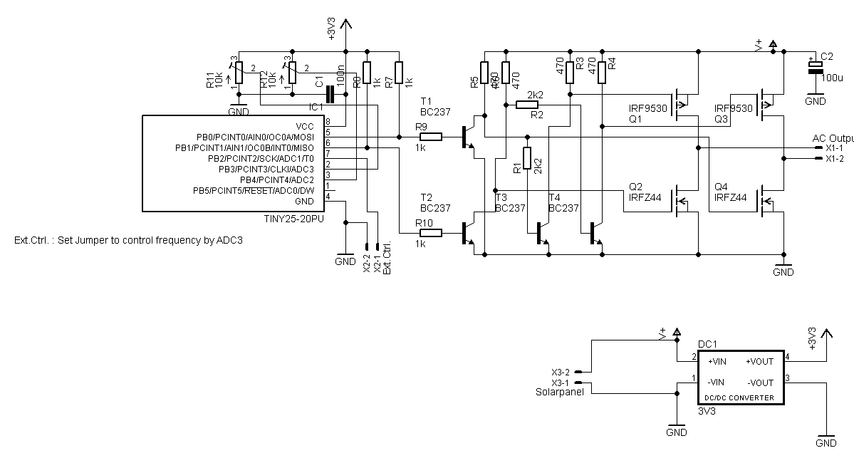
Variable frequency drive with Tiny 25/45/85 ( C )
This C project uses the PWM Timer 0 to generate sine waves using a H-Bridge as power stage. Originally designed to drive a membrane pump for my fish pond with a solar panel it could be modified to build a true sine inverter with the addition of a HV driver like the IR2110/2112 and IGBT or MOSFet powerstages.
The software allows for inverted outputs which i use for the simple drivers as seen in the Schematic Here i use cheap NPN transistors to drive the H-Bridge. By changing the define from USE_INVERTED_OUTPUTS to 0 you could drive a standard output stage. Setting the jumper at PB2 will put the Tiny into external control mode where frequency and amplitude are controlled through ADC channels 2 and 3 resp. Amplitude is always controlled through a pot connected to channel 3 (PB3 = Pin 2) and the optional frequency pot is connected to PB4=Pin3. If the jumper is not set the frequency setting is derived from the internal EEPROM. The current configuration allows settings from 0,1 Hz up to approx. 62 Hz.
By shortening the sine table in VFD_table.h you could achieve higher frequencies while a longer table would more accurately generate sine waves with low frequencies. Formulas are contained in the source code. The project compiles with AVR Studio 4 but it should be easy to adopt for use with AS5 and AS6.
To supply the Tiny with a constant voltage of 3V3 i added a small DC/DC Converter with the MC34063 which is not shown in detail in the schematic. Keep in mind to set the Brown Out Detector in the Tiny when used with a solar panel as a slowly dropping voltage could eventually corrupt the EEPROM when the Tiny is not shutdown properly.
Project ZIP