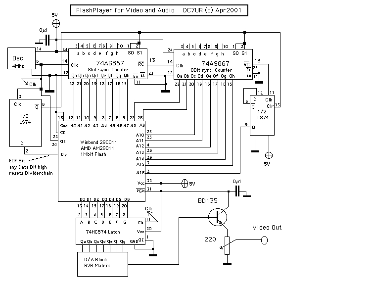
Circuit Diagram
You will notice the usage of the upper 2 bits (D6 and D7). D6 is used to reset the divider chain, while D7 provides the sync signal for the desired TV-Standard. For simplicity, the sync signal is not inverted, so it is high during the active part of display and low in the sync part. This example simply uses the lower 6 bits for a bw display, but it is possible to use 2 bits each for the Red, Green and Blue colour signal via a simple resistor matrix. The 2 synchronous counters are clocked by a standard 4 MHz oscillator.
Most difficult are the necessary calculations to provide a stable TV-picture within the limits of the desired standard. An example PAL picture is provided in this ZIP file. You will need a graphics program capable of writing raw data, e.g. the excellent GraphicsConverter for Macintosh or a similar program for your platform.
Here is an example for the widely used PAL standard: With a 4 Mhz oscillator, each line consists of 256 bytes (64 microseconds), so give your picture a width of 256. The height of the picture is fixed by the TV standard at 312.5 lines, so use 313 as height. This gives (256 * 313) = 80128 bytes, which is perfect for a 128 kByte ROM. Colour depth should be set to 256 colours (8-bytes) to match the data width of the ROM. Now using your Drawing tools set to colour 128 (HEX 0x80), fill the whole picture. To add the horizontal sync signal, draw a 16 pixel wide line on the left border with colour 0. A fine horizontal 3 pixel line on the bottom gives the vertical sync. If you like, add some "satellite sync signals" there to improve picture stability. Refer to the ZIP file and a description of TV standards, if you are interested. Contents of the picture are then drawn with the colours 129 - 191. In the last line now, fill the middle of the line with colour 64. Remember, the exact size was 312.5 lines, right ? This resets the divider chain and starts a new scan.
Feel free to modify this circuit. Think of storing audio in 6 bit format and starting the divider chain with a pushbutton. In any case, let me know of your appliance. This is free hardware, but use at your own risk. In no circumstance I am responsible for any damage and other malfunctions to your properties. Have fun!
Email me for Questions and suggestions.